ros2_control - jazzy
Loading...
Searching...
No Matches
Classes | Typedefs | Functions | Variables
transmission_interface Namespace Reference

Classes

class  ActuatorHandle
 
class  DifferentialTransmission
 
class  DifferentialTransmissionLoader
 Class for loading a four-bar linkage transmission instance from configuration data. More...
 
class  Exception
 
class  FourBarLinkageTransmission
 Implementation of a four-bar-linkage transmission. More...
 
class  FourBarLinkageTransmissionLoader
 Class for loading a four-bar linkage transmission instance from configuration data. More...
 
class  Handle
 
class  JointHandle
 
class  SimpleTransmission
 
class  SimpleTransmissionLoader
 Class for loading a simple transmission instance from configuration data. More...
 
class  Transmission
 Abstract base class for representing mechanical transmissions. More...
 
class  TransmissionInterfaceException
 
class  TransmissionLoader
 Abstract interface for loading transmission instances from configuration data. More...
 

Typedefs

typedef std::shared_ptr< TransmissionTransmissionSharedPtr
 

Functions

template<typename T >
std::string to_string (const std::vector< T > &list)
 
template<class T >
std::vector< std::string > get_names (const std::vector< T > &handles)
 
template<typename T >
std::vector< T > get_ordered_handles (const std::vector< T > &unordered_handles, const std::vector< std::string > &names, const std::string &interface_type)
 
template<class HandleType >
HandleType get_by_interface (const std::vector< HandleType > &handles, const std::string &interface_name)
 
template<class T >
bool are_names_identical (const std::vector< T > &handles)
 

Variables

constexpr auto HW_IF_ABSOLUTE_POSITION = "absolute_position"
 Implementation of a differential transmission.
 

Detailed Description

Author
Adolfo Rodriguez Tsouroukdissian

Variable Documentation

◆ HW_IF_ABSOLUTE_POSITION

constexpr auto transmission_interface::HW_IF_ABSOLUTE_POSITION = "absolute_position"
constexpr

Implementation of a differential transmission.

Implementation of a simple reducer transmission.

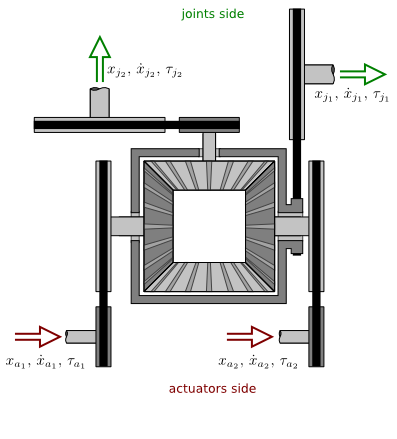
This transmission relates two actuators and two joints through a differential mechanism, as illustrated below.
Effort
Velocity
Position
Actuator to joint

\begin{eqnarray*} \tau_{j_1} & = & n_{j_1} ( n_{a_1} \tau_{a_1} + n_{a_2} \tau_{a_2} ) \\[2.5em] \tau_{j_2} & = & n_{j_2} ( n_{a_1} \tau_{a_1} + n_{a_2} \tau_{a_2} ) \end{eqnarray*}

\begin{eqnarray*} \dot{x}_{j_1} & = & \frac{ \dot{x}_{a_1} / n_{a_1} + \dot{x}_{a_2} / n_{a_2} }{2 n_{j_1}} \\[1em] \dot{x}_{j_2} & = & \frac{ \dot{x}_{a_1} / n_{a_1} - \dot{x}_{a_2} / n_{a_2} }{2 n_{j_2}} \end{eqnarray*}

\begin{eqnarray*} x_{j_1} & = & \frac{ x_{a_1} / n_{a_1} + x_{a_2} / n_{a_2} }{2 n_{j_1}} + x_{off_1} \\[1em] x_{j_2} & = & \frac{ x_{a_1} / n_{a_1} - x_{a_2} / n_{a_2} }{2 n_{j_1}} + x_{off_2} \end{eqnarray*}

Joint to actuator

\begin{eqnarray*} \tau_{a_1} & = & \frac{ \tau_{j_1} / n_{j_1} + \tau_{j_2} / n_{j_2} }{2 n_{a_1}} \\[1em] \tau_{a_2} & = & \frac{ \tau_{j_1} / n_{j_1} - \tau_{j_2} / n_{j_2} }{2 n_{a_1}} \end{eqnarray*}

\begin{eqnarray*} \dot{x}_{a_1} & = & n_{a_1} ( n_{j_1} \dot{x}_{j_1} + n_{j_2} \dot{x}_{j_2} ) \\[2.5em] \dot{x}_{a_2} & = & n_{a_2} ( n_{j_1} \dot{x}_{j_1} - n_{j_2} \dot{x}_{j_2} ) \end{eqnarray*}

\begin{eqnarray*} x_{a_1} & = & n_{a_1} \left[ n_{j_1} (x_{j_1} - x_{off_1}) + n_{j_2} (x_{j_2} - x_{off_2}) \right] \\[2.5em] x_{a_2} & = & n_{a_2} \left[ n_{j_1} (x_{j_1} - x_{off_1}) - n_{j_2} (x_{j_2} - x_{off_2}) \right] \end{eqnarray*}

where:

  • \( x \), \( \dot{x} \) and \( \tau \) are position, velocity and effort variables, respectively.
  • Subindices \( _a \) and \( _j \) are used to represent actuator-space and joint-space variables, respectively.
  • \( x_{off}\) represents the offset between motor and joint zeros, expressed in joint position coordinates (cf. SimpleTransmission class documentation for a more detailed description of this variable).
  • \( n \) represents a transmission ratio. Reducers/amplifiers are allowed on both the actuator and joint sides (depicted as timing belts in the figure). A transmission ratio can take any real value except zero. In particular:
    • If its absolute value is greater than one, it's a velocity reducer / effort amplifier, while if its absolute value lies in \( (0, 1) \) it's a velocity amplifier / effort reducer.
    • Negative values represent a direction flip, ie. input and output move in opposite directions.
    • Important: Use transmission ratio signs to match this class' convention of positive actuator/joint directions with a given mechanical design, as they will in general not match.
Note
This implementation currently assumes a specific layout for location of the actuators and joint axes which is common in robotic mechanisms. Please file an enhancement ticket if your use case does not adhere to this layout.

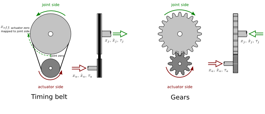
This transmission relates one actuator and one joint through a reductor (or amplifier). Timing belts and gears are examples of this transmission type, and are illustrated below.
Effort
Velocity
Position
Actuator to joint

\[ \tau_j = n \tau_a \]

\[ \dot{x}_j = \dot{x}_a / n \]

\[ x_j = x_a / n + x_{off} \]

Joint to actuator

\[ \tau_a = \tau_j / n\]

\[ \dot{x}_a = n \dot{x}_j \]

\[ x_a = n (x_j - x_{off}) \]

where:

  • \( x \), \( \dot{x} \) and \( \tau \) are position, velocity and effort variables, respectively.
  • Subindices \( _a \) and \( _j \) are used to represent actuator-space and joint-space variables, respectively.
  • \( x_{off}\) represents the offset between motor and joint zeros, expressed in joint position coordinates.
  • \( n \) is the transmission ratio, and can be computed as the ratio between the output and input pulley radii for the timing belt; or the ratio between output and input teeth for the gear system. The transmission ratio can take any real value except zero. In particular:
    • If its absolute value is greater than one, it's a velocity reducer / effort amplifier, while if its absolute value lies in \( (0, 1) \) it's a velocity amplifier / effort reducer.
    • Negative values represent a direction flip, ie. actuator and joint move in opposite directions. For example, in timing belts actuator and joint move in the same direction, while in single-stage gear systems actuator and joint move in opposite directions.