You're reading the documentation for a development version. For the latest released version, please have a look at Kilted.
Getting Started
Installation
Binary packages
The ros2_control framework is released for ROS 2 rolling on Ubuntu and RHEL according to REP-2000.
To use it, you have to install ros-rolling-ros2-control and ros-rolling-ros2-controllers packages, e.g., by running the following commands:
For Ubuntu deb packages
sudo apt install ros-rolling-ros2-control ros-rolling-ros2-controllers
For RHEL (RPM) packages
sudo dnf install ros-rolling-ros2-control ros-rolling-ros2-controllers
Building from Source
The rolling branch is compatible with both Humble and Jazzy ROS distributions. You can find more information about this compatibility on the respective Humble and Jazzy versions of this page.
If you want to install the framework from source, e.g., for contributing to the framework, use the following commands:
Download all repositories
mkdir -p ~/ros2_ws/src
cd ~/ros2_ws/
wget https://raw.githubusercontent.com/ros-controls/ros2_control_ci/master/ros_controls.$ROS_DISTRO.repos
vcs import src < ros_controls.$ROS_DISTRO.repos
Install dependencies:
rosdep update --rosdistro=$ROS_DISTRO
sudo apt-get update
rosdep install --from-paths src --ignore-src -r -y
Build everything, e.g. with:
. /opt/ros/${ROS_DISTRO}/setup.sh
colcon build --symlink-install
Do not forget to source
setup.bashfrom theinstallfolder!
Architecture
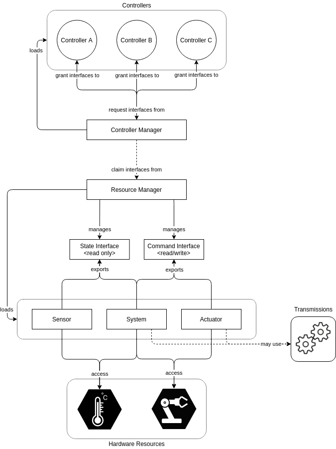
The source code for the ros2_control framework can be found in the ros2_control and ros2_controllers GitHub repositories. The following figure shows the architecture of the ros2_control framework.
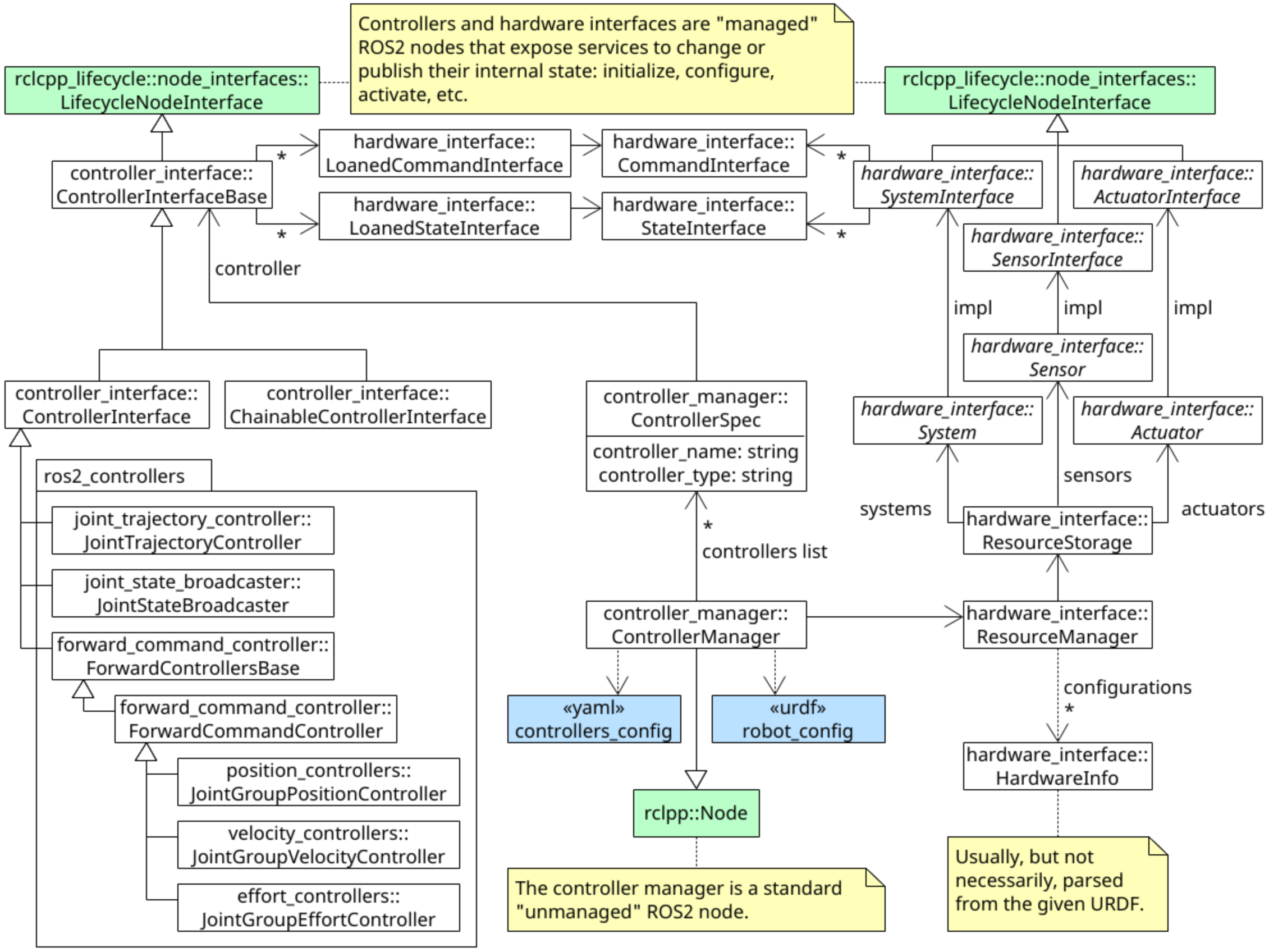
The following UML Class Diagram describes the internal implementation of the ros2_control framework.
Controller Manager
The Controller Manager (CM) connects the controllers and hardware-abstraction sides of the ros2_control framework.
It also serves as the entry-point for users via ROS services.
The CM implements a node without an executor so that it can be integrated into a custom setup.
However, it’s usually recommended to use the default node-setup implemented in ros2_control_node file from the controller_manager package.
This manual assumes that you use this default node-setup.
On the one hand, CM manages (e.g. loads, activates, deactivates, unloads) controllers and the interfaces they require. On the other hand, it has access (via the Resource Manager) to the hardware components, i.e. their interfaces. The Controller Manager matches required and provided interfaces, granting controllers access to hardware when enabled, or reporting an error if there is an access conflict.
The execution of the control-loop is managed by the CM’s update() method.
It reads data from the hardware components, updates outputs of all active controllers, and writes the result to the components.
Resource Manager
The Resource Manager (RM) abstracts physical hardware and its drivers (called hardware components) for the ros2_control framework.
The RM loads the components using the pluginlib-library, manages their lifecycle and components’ state and command interfaces.
The abstraction provided by RM allows reuse of implemented hardware components, e.g., robot and gripper, without any implementation, and flexible hardware application for state and command interfaces, e.g., separate hardware/communication libraries for motor control and encoder reading.
In the control loop execution, the RM’s read() and write() methods handle the communication with the hardware components.
Controllers
The controllers in the ros2_control framework are based on control theory. They compare the reference value with the measured output and, based on this error, calculate a system’s input.
The controllers are objects derived from ControllerInterface (controller_interface package in ros2_control) and exported as plugins using pluginlib-library.
For an example of a controller check the ForwardCommandController implementation in the ros2_controllers repository.
The controller lifecycle is based on the LifecycleNode class, which implements the state machine described in the Node Lifecycle Design document.
When the control-loop is executed, the update() method is called.
This method can access the latest hardware state and enable the controller to write to the hardware command interfaces.
User Interfaces
Users interact with the ros2_control framework using Controller Manager’s services.
For a list of services and their definitions, check the srv folder in the controller_manager_msgs package.
While service calls can be used directly from the command line or via nodes, there exists a user-friendly Command Line Interface (CLI) which integrates with the ros2 cli. This supports auto-complete and has a range of common commands available. The base command is ros2 control.
For the description of our CLI capabilities, see the Command Line Interface (CLI) documentation.
Hardware Components
The hardware components realize communication to physical hardware and represent its abstraction in the ros2_control framework.
The components have to be exported as plugins using pluginlib-library.
The Resource Manager dynamically loads those plugins and manages their lifecycle.
There are three basic types of components:
- System
Complex (multi-DOF) robotic hardware like industrial robots. The main difference between the Actuator component is the possibility to use complex transmissions like needed for humanoid robot’s hands. This component has reading and writing capabilities. It is used when there is only one logical communication channel to the hardware (e.g., KUKA-RSI).
- Sensor
Robotic hardware is used for sensing its environment. A sensor component is related to a joint (e.g., encoder) or a link (e.g., force-torque sensor). This component type has only reading capabilities.
- Actuator
Simple (1 DOF) robotic hardware like motors, valves, and similar. An actuator implementation is related to only one joint. This component type has reading and writing capabilities. Reading is not mandatory if not possible (e.g., DC motor control with Arduino board). The actuator type can also be used with a multi-DOF robot if its hardware enables modular design, e.g., CAN-communication with each motor independently.
A detailed explanation of hardware components is given in the Hardware Access through Controllers design document.
Hardware Description in URDF
The ros2_control framework uses the <ros2_control>-tag in the robot’s URDF file to describe its components, i.e., the hardware setup.
The chosen structure enables tracking together multiple xacro-macros into one without any changes.
The example hereunder shows a position-controlled robot with 2-DOF (RRBot), an external 1-DOF force-torque sensor, and an externally controlled 1-DOF parallel gripper as its end-effector.
For more examples and detailed explanations, check the ros2_control_demos site and ROS 2 Control Components URDF Examples design document.
<ros2_control name="RRBotSystemPositionOnly" type="system">
 <hardware>
   <plugin>ros2_control_demo_hardware/RRBotSystemPositionOnlyHardware</plugin>
   <param name="example_param_write_for_sec">2</param>
   <param name="example_param_read_for_sec">2</param>
 </hardware>
 <joint name="joint1">
   <command_interface name="position">
     <param name="min">-1</param>
     <param name="max">1</param>
   </command_interface>
   <state_interface name="position"/>
 </joint>
 <joint name="joint2">
   <command_interface name="position">
     <param name="min">-1</param>
     <param name="max">1</param>
   </command_interface>
   <state_interface name="position"/>
 </joint>
</ros2_control>
<ros2_control name="RRBotForceTorqueSensor1D" type="sensor">
 <hardware>
   <plugin>ros2_control_demo_hardware/ForceTorqueSensor1DHardware</plugin>
   <param name="example_param_read_for_sec">0.43</param>
 </hardware>
 <sensor name="tcp_fts_sensor">
   <state_interface name="force"/>
   <param name="frame_id">rrbot_tcp</param>
   <param name="min_force">-100</param>
   <param name="max_force">100</param>
 </sensor>
</ros2_control>
<ros2_control name="RRBotGripper" type="actuator">
 <hardware>
   <plugin>ros2_control_demo_hardware/PositionActuatorHardware</plugin>
   <param name="example_param_write_for_sec">1.23</param>
   <param name="example_param_read_for_sec">3</param>
 </hardware>
 <joint name="gripper_joint ">
   <command_interface name="position">
     <param name="min">0</param>
     <param name="max">50</param>
   </command_interface>
   <state_interface name="position"/>
   <state_interface name="velocity"/>
 </joint>
</ros2_control>
Running the Framework for Your Robot
To run the ros2_control framework, do the following. The example files can be found in the ros2_control_demos repository.
Create a YAML file with the configuration of the controller manager and two controllers. (Example configuration for RRBot)
Extend the robot’s URDF description with needed
<ros2_control>tags. It is recommended to use macro files (xacro) instead of pure URDF. (Example URDF for RRBot)Create a launch file to start the node with Controller Manager. You can use a default ros2_control node (recommended) or integrate the controller manager in your software stack. (Example launch file for RRBot)
NOTE: You could alternatively use a script to create setup a skeleton of the “robot bringup” package by using the scripts provided by one of our maintainers. Extension of xacro for ros2_control file you can find in the templates for “robot description” package.