You're reading the documentation for an older, but still supported, version of ROS 2. For information on the latest version, please have a look at Kilted.
Example 5: Industrial robot with externally connected sensor
This example shows how an externally connected sensor can be accessed:
The communication is done using proprietary API to communicate with the robot control box.
Data for all joints is exchanged at once.
Sensor data are exchanged independently of joint data.
Examples: KUKA RSI and FTS connected to independent PC with ROS 2.
A 3D Force-Torque Sensor (FTS) is simulated by generating random sensor readings via a hardware interface of
type hardware_interface::SensorInterface.
Note
The commands below are given for a local installation of this repository and its dependencies as well as for running them from a docker container. For more information on the docker usage see Using Docker.
Tutorial steps
To check that RRBot descriptions are working properly use following launch commands
ros2 launch ros2_control_demo_example_5 view_robot.launch.py
Note
Getting the following output in terminal is OK:
Warning: Invalid frame ID "odom" passed to canTransform argument target_frame - frame does not exist. This happens becausejoint_state_publisher_guinode need some time to start. Thejoint_state_publisher_guiprovides a GUI to generate a random configuration for rrbot. It is immediately displayed in RViz.To start RRBot example open a terminal, source your ROS2-workspace and execute its launch file with
ros2 launch ros2_control_demo_example_5 rrbot_system_with_external_sensor.launch.py
The launch file loads and starts the robot hardware, controllers and opens RViz. In starting terminal you will see a lot of output from the hardware implementation showing its internal states. This is only of exemplary purposes and should be avoided as much as possible in a hardware interface implementation.
If you can see two orange and one yellow rectangle in in RViz everything has started properly. Still, to be sure, let’s introspect the control system before moving RRBot.
Note
The launch file supports an optional
use_wrench_transformerargument to enable the wrench transformer node. See step 7 for details on using the wrench transformer feature.Check if the hardware interface loaded properly, by opening another terminal and executing
ros2 control list_hardware_interfaces
command interfaces
  joint1/position [available] [claimed]
  joint2/position [available] [claimed]
state interfaces
  joint1/position
  joint2/position
  tcp_fts_sensor/force.x
  tcp_fts_sensor/force.y
  tcp_fts_sensor/force.z
  tcp_fts_sensor/torque.x
  tcp_fts_sensor/torque.y
Marker
[claimed]by command interfaces means that a controller has access to command RRBot.Now, let’s introspect the hardware components with
ros2 control list_hardware_components
There are two hardware components, one for the robot and one for the sensor:
Hardware Component 1
        name: ExternalRRBotFTSensor
        type: sensor
        plugin name: ros2_control_demo_example_5/ExternalRRBotForceTorqueSensorHardware
        state: id=3 label=active
        command interfaces
Hardware Component 2
        name: RRBotSystemPositionOnly
        type: system
        plugin name: ros2_control_demo_example_5/RRBotSystemPositionOnlyHardware
        state: id=3 label=active
        command interfaces
                joint1/position [available] [claimed]
                joint2/position [available] [claimed]
Check if controllers are running
ros2 control list_controllers
forward_position_controller[forward_command_controller/ForwardCommandController] active
fts_broadcaster[force_torque_sensor_broadcaster/ForceTorqueSensorBroadcaster] active
joint_state_broadcaster[joint_state_broadcaster/JointStateBroadcaster] active
If you get output from above you can send commands to Forward Command Controller, either:
Manually using ROS 2 CLI interface.
ros2 topic pub /forward_position_controller/commands std_msgs/msg/Float64MultiArray "data:
- 0.5
- 0.5"
Or you can start a demo node which sends two goals every 5 seconds in a loop
ros2 launch ros2_control_demo_example_5 test_forward_position_controller.launch.py
You should now see orange and yellow blocks moving in RViz. Also, you should see changing states in the terminal where launch file is started, e.g.
[ros2_control_node-1] [INFO] [1721764191.201301188] [controller_manager.resource_manager.hardware_component.system.RRBotSystemPositionOnly]: Writing commands:
[ros2_control_node-1]   0.50 for joint 'joint1'
[ros2_control_node-1]   0.50 for joint 'joint2'
Access wrench data from 2D FTS via
ros2 topic echo /fts_broadcaster/wrench
shows the random generated sensor values, republished by Force Torque Sensor Broadcaster as
geometry_msgs/msg/WrenchStampedmessageheader: stamp: sec: 1676444704 nanosec: 332221422 frame_id: tool_link wrench: force: x: 1.2126582860946655 y: 2.3202226161956787 z: 3.4302282333374023 torque: x: 4.540233612060547 y: 0.647800624370575 z: 1.7602499723434448
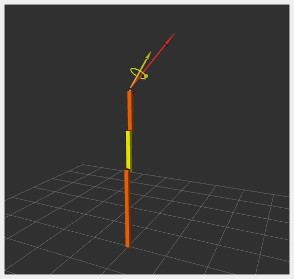
Wrench data are also visualized in RViz:
Access transformed wrench data in different frames using the Wrench Transformer Node (optional):
The launch file can optionally start a
wrench_transformer_nodethat transforms wrench messages from the sensor frame (tool_link) to other target frames using TF2. This feature is disabled by default.To enable the wrench transformer, launch with the
use_wrench_transformerargument:ros2 launch ros2_control_demo_example_5 rrbot_system_with_external_sensor.launch.py use_wrench_transformer:=true
Once enabled, check available transformed wrench topics:
ros2 topic list | grep wrench
You should see topics like:
/fts_wrench_transformer/base_link/wrench
/fts_wrench_transformer/link1/wrench
View transformed wrench data in the
base_linkframe:ros2 topic echo /fts_wrench_transformer/base_link/wrench
The transformed wrench messages will have the same structure as the original wrench, but with
frame_idset to the target frame (e.g.,base_link) and the force/torque values transformed to that coordinate frame.header: stamp: sec: 1676444704 nanosec: 332221422 frame_id: base_link wrench: force: x: <transformed_value> y: <transformed_value> z: <transformed_value> torque: x: <transformed_value> y: <transformed_value> z: <transformed_value>
The wrench transformer configuration can be customized in the parameter file: wrench_transformer_params.yaml
Files used for this demos
Launch file: rrbot_system_with_external_sensor.launch.py
Controllers yaml: rrbot_with_external_sensor_controllers.yaml
Wrench transformer params: wrench_transformer_params.yaml
URDF: rrbot_with_external_sensor_controllers.urdf.xacro
Description: rrbot_description.urdf.xacro
ros2_controlrobot: rrbot_system_position_only.ros2_control.xacroros2_controlsensor: external_rrbot_force_torque_sensor.ros2_control.xacro
RViz configuration: rrbot.rviz
Hardware interface plugin:
robot rrbot.cpp
Controllers from this demo
Joint State Broadcaster(ros2_controllers repository): docForward Command Controller(ros2_controllers repository): docForce Torque Sensor Broadcaster(ros2_controllers repository): doc