You're reading the documentation for a development version. For the latest released version, please have a look at Kilted.
Example 7: Full tutorial with a 6DOF robot
ros2_control is a realtime control framework designed for general robotics applications. Standard c++ interfaces exist for interacting with hardware and querying user defined controller commands. These interfaces enhance code modularity and robot agnostic design. Application specific details, e.g. what controller to use, how many joints a robot has and their kinematic structure, are specified via YAML parameter configuration files and a Universal Robot Description File (URDF). Finally, the ros2_control framework is deployed via ROS 2 launch a file.
This tutorial will address each component of ros2_control in detail, namely:
ros2_control overview
Writing a URDF
Writing a hardware interface
Writing a controller
ros2_control overview
ros2_control introduces state_interfaces and command_interfaces to abstract hardware interfacing. The state_interfaces are read only data handles that generally represent sensors readings, e.g. joint encoder. The command_interfaces are read and write data handles that hardware commands, like setting a joint velocity reference. The command_interfaces are exclusively accessed, meaning if a controller has “claimed” an interface, it cannot be used by any other controller until it is released. Both interface types are uniquely designated with a name and type. The names and types for all available state and command interfaces are specified in a YAML configuration file and a URDF file.
ros2_control provides the ControllerInterface and HardwareInterface classes for robot agnostic control. During initialization, controllers request state_interfaces and command_interfaces required for operation through the ControllerInterface. On the other hand, hardware drivers offer state_interfaces and command_interfaces via the HardwareInterface. ros2_control ensure all requested interfaces are available before starting the controllers. The interface pattern allows vendors to write hardware specific drivers that are loaded at runtime.
The main program is a realtime read, update, write loop. During the read call, hardware drivers that conform to HardwareInterface update their offered state_interfaces with the newest values received from the hardware. During the update call, controllers calculate commands from the updated state_interfaces and writes them into its command_interfaces. Finally, during to write call, the hardware drivers read values from the command_interfaces and sends them to the hardware. The ros2_control_node runs the main loop in a realtime thread. The ros2_control_node runs a second non-realtime thread to interact with ROS publishers, subscribers, and services.
Writing a URDF
The URDF file is a standard XML based file used to describe characteristic of a robot. It can represent any robot with a tree structure, except those with cycles. Each link must have only one parent. For ros2_control, there are three primary tags: link, joint, and ros2_control. The joint tag define the robot’s kinematic structure, while the link tag defines the dynamic properties and 3D geometry. The ros2_control defines the hardware and controller configuration.
Geometry
Most commercial robots already have robot_description packages defined, see the Universal Robots for an example. However, this tutorial will go through the details of creating one from scratch.
First, we need a 3D model of our robot. For illustration, a generic 6 DOF robot manipulator will be used.
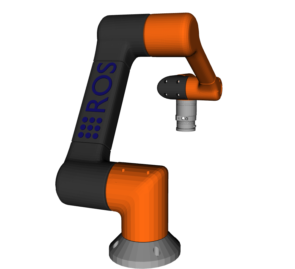
a generic 6 DOF robot manipulator
The robot’s 6 links each need to be processed and exported to their own .stl and .dae files. Generally, the .stl 3D model files are coarse meshes used for fast collision checking, while the .dae files are used for visualization purposed only. We will use the same mesh in our case for simplicity.
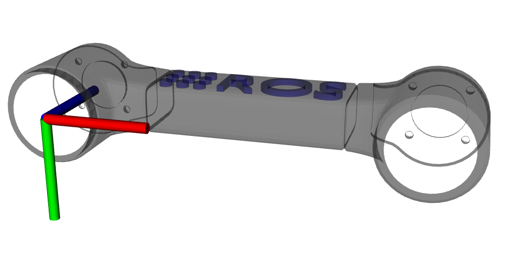
By convention, each .stl file expresses the position its vertices in its own reference frame. Hence, we need to specify the linear transformation (rotation and translation) between each link to define the robot’s full geometry. The 3D model for each link should be adjusted such that the proximal joint axis (the axis that connects the link to its parent) is in the z-axis direction. The 3D model’s origin should also be adjusted such that the bottom face of the mesh is co-planer with the xy-plane. The following mesh illustrates this configuration.
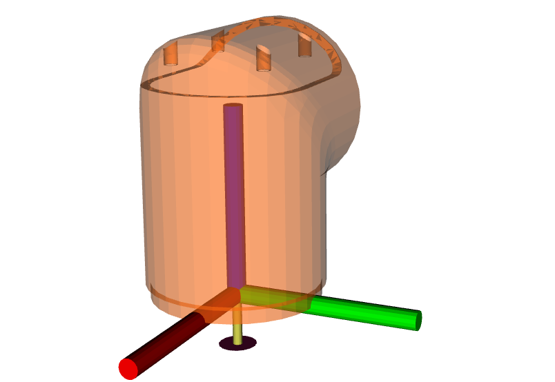
Link 1
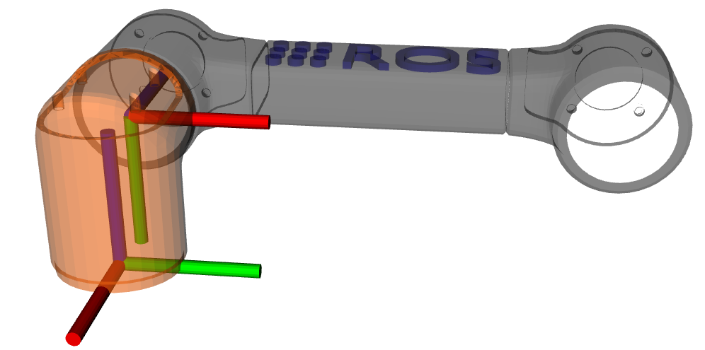
Link 2 aligned
Each mesh should be exported to its own file after processing them. Blender is an open source 3D modeling software, which can import/export .stl and .dae files and manipulate their vertices. Blender was used to process the robot model in this tutorial.
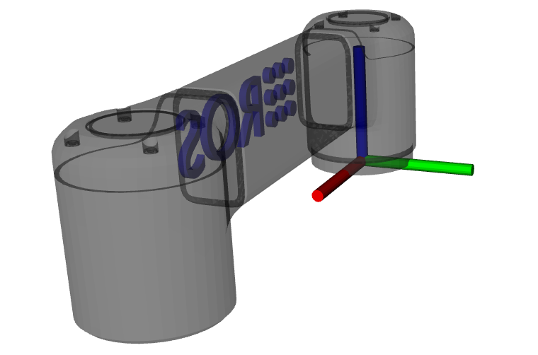
We can finally calculate the transforms between the robot’s joints and begin writing the URDF. First, apply a negative 90 degree roll to link 2 in its frame.
Link 2 with -90 degree roll
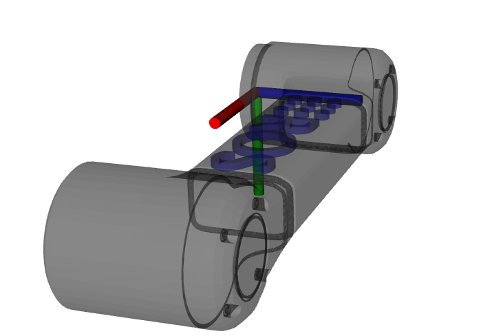
To keep the example simple, we will not apply a pitch now. Then, we apply a positive 90 degree yaw.
Link 2 with -90 degree roll and 90 degree yaw
Finally, we apply a translation of -0.1 meters in the x-axis and 0.18 meters in the z-axis between the link 2 and link 1 frame. The final result is shown below.
Link 2 with -90 degree roll, 90 degree yaw, and translation
The described process is then repeated for all links.
URDF file
The URDF file is generally formatted according to the following template.
<robot name="robot_6_dof">
  <!-- create link fixed to the "world" -->
  <link name="base_link">
    <visual>
      <origin rpy="0 0 0" xyz="0 0 0"/>
      <geometry>
        <mesh filename="package://robot_6_dof/meshes/visual/link_0.dae"/>
      </geometry>
    </visual>
    <collision>
      <origin rpy="0 0 0" xyz="0 0 0"/>
      <geometry>
        <mesh filename="package://robot_6_dof/meshes/collision/link_0.stl"/>
      </geometry>
    </collision>
    <inertial>
      <mass value="1"/>
      <inertia ixx="1.0" ixy="0.0" ixz="0.0" iyy="1.0" iyz="0.0" izz="1.0"/>
    </inertial>
  </link>
  <!-- additional links ... -->
  <link name="world"/>
  <link name="tool0"/>
  <joint name="base_joint" type="fixed">
    <parent link="world"/>
    <child link="base_link"/>
    <origin rpy="0 0 0" xyz="0 0 0"/>
    <axis xyz="0 0 1"/>
  </joint>
  <!-- joints - main serial chain -->
  <joint name="joint_1" type="revolute">
    <parent link="base_link"/>
    <child link="link_1"/>
    <origin rpy="0 0 0" xyz="0 0 0.061584"/>
    <axis xyz="0 0 1"/>
    <limit effort="1000.0" lower="-3.141592653589793" upper="3.141592653589793" velocity="2.5"/>
  </joint>
  <!-- additional joints ... -->
  <!-- ros2 control tag -->
  <ros2_control name="robot_6_dof" type="system">
    <hardware>
      <plugin>
        <!-- {Name_Space}/{Class_Name}-->
      </plugin>
    </hardware>
    <joint name="joint_1">
      <command_interface name="position">
        <param name="min">{-2*pi}</param>
        <param name="max">{2*pi}</param>
      </command_interface>
      <!-- additional command interfaces ... -->
      <state_interface name="position">
        <param name="initial_value">0.0</param>
      </state_interface>
      <!-- additional state interfaces ... -->
    </joint>
    <!-- additional joints ...-->
    <!-- additional hardware/sensors ...-->
  </ros2_control>
</robot>
The
robottag encloses all contents of the URDF file. It has a name attribute which must be specified.The
linktag defines the robot’s geometry and inertia properties. It has a name attribute which will be referred to by thejointtags.The
visualtag specifies the rotation and translation of the visual mesh. If the meshes were process as described previously, then theorigintag can be left at all zeros.The
geometryandmeshtags specify the location of the 3D mesh file relative to a specified ROS 2 package.The
collisiontag is equivalent to thevisualtag, except the specified mesh is used for collision checking in some applications.The
inertialtag specifies mass and inertia for the link. The origin tag specifies the link’s center of mass. These values are used to calculate forward and inverse dynamics. Since our application does not use dynamics, uniform arbitrary values are used.The
<!-- additional links ... -->comments indicates that many consecutivelinktags will be defined, one for each link.The
<link name="world"/>and<link name="tool0"/>elements are not required. However, it is convention to set the link at the tip of the robot to tool0 and to define the robot’s base link relative to a world frame.The
jointtag specifies the kinematic structure of the robot. It has two required attributes: name and type. The type specifies the viable motion between the two connected links. The subsequentparentandchildlinks specify which two links are joined by the joint.The
axistag species the joint’s degree of freedom. If the meshes were process as described previously, then the axis value is always"0 0 1".The
limitstag specifies kinematic and dynamics limits for the joint.The
ros2_controltag specifies hardware configuration of the robot. More specifically, the available state and command interfaces. The tag has two required attributes: name and type. Additional elements, such as sensors, are also included in this tag.The
hardwareandplugintags instruct the ros2_control framework to dynamically load a hardware driver conforming toHardwareInterfaceas a plugin. The plugin is specified as<{Name_Space}/{Class_Name}.Finally, the
jointtag specifies the state and command interfaces that the loaded plugins will offer. The joint is specified with the name attribute. Thecommand_interfaceandstate_interfacetags specify the interface type, usually position, velocity, acceleration, or effort.
To simplify the URDF file, xacro is used to define macros, see this tutorial. The complete xacro file for the robot in this tutorial is available here. To verify the kinematic chain, the tool urdf_to_graphviz can be used after the URDF is generated by xacro. Running
xacro description/urdf/r6bot.urdf.xacro > r6bot.urdf
urdf_to_graphviz r6bot.urdf r6bot
generates r6bot.pdf, showing the kinematic chain of the robot.
Writing a hardware interface
In ros2_control, hardware system components are integrated via user defined driver plugins that conform to the HardwareInterface public interface. Hardware plugins specified in the URDF are dynamically loaded during initialization using the pluginlib interface. In order to run the ros2_control_node, a parameter named robot_description must be set. This normally done in the ros2_control launch file.
The following code blocks will explain the requirements for writing a new hardware interface.
The hardware plugin for the tutorial robot is a class called RobotSystem that inherits from hardware_interface::SystemInterface. The SystemInterface is one of the offered hardware interfaces designed for a complete robot system. For example, The UR5 uses this interface. The RobotSystem must implement the following public methods.
on_initon_configurereadwrite
There are more methods that can be implemented for lifecycle changes, but they are not required for the tutorial robot.
using CallbackReturn = rclcpp_lifecycle::node_interfaces::LifecycleNodeInterface::CallbackReturn;
#include "hardware_interface/types/hardware_interface_return_values.hpp"

class RobotSystem : public hardware_interface::SystemInterface {
    public:
    CallbackReturn on_init(hardware_interface::HardwareComponentInterfaceParams & params) override;
    CallbackReturn on_configure(const rclcpp_lifecycle::State & previous_state) override;
    return_type read(const rclcpp::Time &time, const rclcpp::Duration &period) override;
    return_type write(const rclcpp::Time & /*time*/, const rclcpp::Duration & /*period*/) override;
    // private members
    // ...
}
The on_init method is called once during ros2_control initialization if the RobotSystem was specified in the URDF. In this method, communication between the robot hardware needs to be setup and memory dynamic should be allocated. Since the tutorial robot is simulated, explicit communication will not be established.
CallbackReturn RobotSystem::on_init(hardware_interface::HardwareComponentInterfaceParams & params) {
    if (hardware_interface::SystemInterface::on_init(params) != CallbackReturn::SUCCESS) {
        return CallbackReturn::ERROR;
    }
    // setup communication with robot hardware
    // ...
    return CallbackReturn::SUCCESS;
}
Notably, the behavior of on_init is expected to vary depending on the URDF file. The SystemInterface::on_init(info) call fills out the info object with specifics from the URDF. For example, the info object has fields for joints, sensors, gpios, and more. Suppose the sensor field has a name value of tcp_force_torque_sensor. Then the on_init must try to establish communication with that sensor. If it fails, then an error value is returned.
The on_configure method is called once during ros2_control lifecycle of the RobotSystem. Initial values are set for state and command interfaces that represent the state all the hardware, e.g. doubles describing joint angles, etc.
CallbackReturn RobotSystem::on_configure(
  const rclcpp_lifecycle::State & /*previous_state*/)
    // setup communication with robot hardware
    // ...
    return CallbackReturn::SUCCESS;
}
The read method is core method in the ros2_control loop. During the main loop, ros2_control loops over all hardware components and calls the read method. It is executed on the realtime thread, hence the method must obey by realtime constraints. The read method is responsible for updating the data values of the state_interfaces. Since the data value point to class member variables, those values can be filled with their corresponding sensor values, which will in turn update the values of each exported StateInterface object.
return_type RobotSystem::read(const rclcpp::Time & time, const rclcpp::Duration &period) {
    // read hardware values for state interfaces, e.g joint encoders and sensor readings
    // ...
    return return_type::OK;
}
The write method is another core method in the ros2_control loop. It is called after update in the realtime loop. For this reason, it must also obey by realtime constraints. The write method is responsible for updating the data values of the command_interfaces. As opposed to read, write accesses data values pointer to by the exported CommandInterface objects sends them to the corresponding hardware. For example, if the hardware supports setting a joint velocity via TCP, then this method accesses data of the corresponding command_interface and sends a packet with the value.
return_type write(const rclcpp::Time & time, const rclcpp::Duration & period) {
    // send command interface values to hardware, e.g joint set joint velocity
    // ...
    return return_type::OK;
}
Finally, all ros2_control plugins should have the following two lines of code at the end of the file.
#include "pluginlib/class_list_macros.hpp"

PLUGINLIB_EXPORT_CLASS(robot_6_dof_hardware::RobotSystem, hardware_interface::SystemInterface)
PLUGINLIB_EXPORT_CLASS is a c++ macro creates a plugin library using pluginlib.
Plugin description file (hardware)
The plugin description file is a required XML file that describes a plugin’s library name, class type, namespace, description, and interface type. This file allows the ROS 2 to automatically discover and load plugins. It is formatted as follows.
<library path="{Library_Name}">
  <class
    name="{Namespace}/{Class_Name}"
    type="{Namespace}::{Class_Name}"
    base_class_type="hardware_interface::SystemInterface">
  <description>
    {Human readable description}
  </description>
  </class>
</library>
The path attribute of the library tags refers to the cmake library name of the user defined hardware plugin. See here for the complete XML file.
CMake library (hardware)
The general CMake template to make a hardware plugin available in ros2_control is shown below. Notice that a library is created using the plugin source code just like any other cmake library. In addition, an extra compile definition and cmake export macro (pluginlib_export_plugin_description_file) need to be added. See here for the complete CMakeLists.txt file.
add_library(
    robot_6_dof_hardware
    SHARED
    src/robot_hardware.cpp
)
Writing a controller
In ros2_control, controllers are implemented as plugins that conform to the ControllerInterface public interface. Similar to the hardware interfaces, the controller plugins to load are specified using ROS parameters. This is normally achieved by passing a YAML parameter file to the ros2_control_node. Unlike hardware interfaces, controllers exists in a finite set of states:
Unconfigured
Inactive
Active
Finalized
Certain interface methods are called during transitions between these states. During the main control loop, the controller is in the active state.
The following code blocks will explain the requirements for writing a new controller.
The controller plugin for the tutorial robot is a class called RobotController that inherits from controller_interface::ControllerInterface. The RobotController must implement the following public methods:
command_interface_configurationstate_interface_configurationupdate
The following methods are managed node transitions callbacks. These overrides are optional and only the on_configure, on_activate and on_deactivate have been used in this example.
The on_cleanup and on_shutdown methods are called when the controller’s lifecycle node transitions to the shutdown state. They should handle memory deallocation and general cleanup. The on_error method is invoked if the managed node encounters a failure during a state transition.
on_configureon_activateon_deactivateon_cleanupon_erroron_shutdown
class RobotController : public controller_interface::ControllerInterface {
    public:
    controller_interface::InterfaceConfiguration command_interface_configuration() const override;
    controller_interface::InterfaceConfiguration state_interface_configuration() const override;
    controller_interface::return_type update(const rclcpp::Time &time, const rclcpp::Duration &period) override;
    controller_interface::CallbackReturn on_init() override;
    controller_interface::CallbackReturn on_configure(const rclcpp_lifecycle::State &previous_state) override;
    controller_interface::CallbackReturn on_activate(const rclcpp_lifecycle::State &previous_state) override;
    controller_interface::CallbackReturn on_deactivate(const rclcpp_lifecycle::State &previous_state) override;
// private members
// ...
}
The on_init method is called immediately after the controller plugin is dynamically loaded. The method is called only once during the lifetime for the controller, hence memory that exists for the lifetime of the controller should be allocated. Additionally, the parameter values for joints, command_interfaces and state_interfaces should be declared and accessed. Those parameter values are required for the next two methods.
using CallbackReturn = rclcpp_lifecycle::node_interfaces::LifecycleNodeInterface::CallbackReturn;

controller_interface::CallbackReturn on_init(){
    // declare and get parameters needed for controller initialization
    // allocate memory that will exist for the life of the controller
    // ...
    return CallbackReturn::SUCCESS;
}
The on_configure method is called immediately after the controller is set to the inactive state. This state occurs when the controller is started for the first time, but also when it is restarted. Reconfigurable parameters should be read in this method. Additionally, publishers and subscribers should be created.
controller_interface::CallbackReturn on_configure(const rclcpp_lifecycle::State &previous_state){
    // declare and get parameters needed for controller operations
    // setup realtime buffers, ROS publishers, and ROS subscribers
    // ...
  return CallbackReturn::SUCCESS;
}
The command_interface_configuration method is called after on_configure. The method returns a list of InterfaceConfiguration objects to indicate which command interfaces the controller needs to operate. The command interfaces are uniquely identified by their name and interface type. If a requested interface is not offered by a loaded hardware interface, then the controller will fail.
controller_interface::InterfaceConfiguration command_interface_configuration(){
    controller_interface::InterfaceConfiguration conf;
    // add required command interface to `conf` by specifying their names and interface types.
    // ..
    return conf
}
The state_interface_configuration method is then called, which is similar to the last method. The difference is that a list of InterfaceConfiguration objects representing the required state interfaces to operate is returned.
controller_interface::InterfaceConfiguration state_interface_configuration() {
    controller_interface::InterfaceConfiguration conf;
    // add required state interface to `conf` by specifying their names and interface types.
    // ..
    return conf
}
The on_activate is called once when the controller is activated. This method should handle controller restarts, such as setting the resetting reference to safe values. It should also perform controller specific safety checks. The command_interface_configuration and state_interface_configuration methods are also called again when the controller is activated.
controller_interface::CallbackReturn on_activate(const rclcpp_lifecycle::State &previous_state){
  // Handle controller restarts and dynamic parameter updating
  // ...
  return CallbackReturn::SUCCESS;
}
The update method is part of the main control loop. Since the method is part of the realtime control loop, the realtime constraint must be enforced. The controller should read from its state interfaces, read its reference and calculate a control output. Normally, the reference is accessed via a ROS 2 subscriber. Since the subscriber runs on the non-realtime thread, a realtime buffer is used to a transfer the message to the realtime thread. The realtime buffer is eventually a pointer to a ROS message with a mutex that guarantees thread safety and that the realtime thread is never blocked. The calculated control output should then be written to the command interface, which will in turn control the hardware.
controller_interface::return_type update(const rclcpp::Time &time, const rclcpp::Duration &period){
  // Read controller inputs values from state interfaces
  // Calculate controller output values and write them to command interfaces
  // ...
  return controller_interface::return_type::OK;
}
The on_deactivate is called when a controller stops running. In our case it is empty:
controller_interface::CallbackReturn on_deactivate(const rclcpp_lifecycle::State &previous_state){
    // The controller should be properly shutdown during this
    // ...
    return CallbackReturn::SUCCESS;
}
Plugin description file (controller)
The plugin description file is again required for the controller, since it is exported as a library. The controller plugin description file is formatted as follows. See here for the complete XML file.
<library path="{Library_Name}">
  <class
    name="{Namespace}/{Class_Name}"
    type="{Namespace}::{Class_Name}"
    base_class_type="controller_interface::ControllerInterface">
  <description>
    {Human readable description}
  </description>
  </class>
</library>
CMake library (controller)
The plugin must be specified in the CMake file that builds the controller plugin. See here for the complete CMakeLists.txt file.
add_library(
    r6bot_controller
    SHARED
    src/robot_controller.cpp
)
Launching the example
The full tutorial example can be run by first building the workspace.
git clone -b master https://github.com/ros-controls/ros2_control_demos.git
cd ros2_control_demos
colcon build --symlink-install
source install/setup.bash
To view the robot, open a terminal and launch the view_r6bot.launch.py file from the ros2_control_demo_example_7 package.
ros2 launch ros2_control_demo_example_7 view_r6bot.launch.py
With the joint_state_publisher_gui you can now change the position of every joint.
Next, kill the process in the launch file and start the simulation of the controlled robot.
Open a terminal and launch the r6bot_controller.launch.py file from the ros2_control_demo_example_7 package.
ros2 launch ros2_control_demo_example_7 r6bot_controller.launch.py
Finally, open a new terminal and run the following command.
ros2 launch ros2_control_demo_example_7 send_trajectory.launch.py
You should see the tutorial robot making a circular motion in RViz.
Trajectory following example.